
No Pulses/Flow Being Detected or Device Constantly Detecting Pulses
Symptoms
- Pulser board not reading
- Unauthorized pulses
- Liters/pulses not being tracked
- Not detecting flow on single slot
- Fuel Lock device (screen) not showing liters
Possible Causes
- Faulty flow meter board
- Disconnected J16
- J16 connector not connected properly / the right way
- On the main board, slots wired to the top connector instead of the bottom of the two
- Tanks not set up / configured properly in the Fuel Lock app
- Wiring issue
Troubleshooting
See video on troubleshooting No Flow issue.
Confirm the Fuel Lock app has been configured properly
- The fuel Lock app needs to be set up and configured correctly. Please check out this video on how to add/manage devices
- If new install or changes have been recently made, ensure a successful sync is done. See Manual Sync.
Perform Flow Test
Fuel Lock devices are equipped with an on-board install/troubleshooting menu designed to assist installers and electricians with initial install and calibration of the device, as well as field troubleshooting if hardware fails during operation.
For information on how to do a Flow Test, check out this video.
Notes:
- This tool does not require any Fuel Lock App connectivity
- Flow Test tool is only available for FW 17 and up
The following procedure shows the calibration of custom pulse rates, as well as the verification of third-party pulser functionality with the Fuel Lock device.
Note: The menu is specifically designed for Fuel Lock installers and can be accessed by using the factory default PIN. The default PIN is 1234 if the device has not previously been connected to the mobile app.
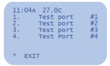
- Press * Menu and enter the Admin PIN
- Press #
- Select #5 Install Support
- Select #1 Tank Calibration
- Ensure the selected port has a pulser that is physically connected to the pulser circuit board inside the Fuel Lock device
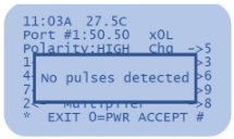
When first entering each Test Port menu, the screen will flash “No pulses detected”. This indicates that the pulser connected to the Fuel Lock pulser board is not generating pulses (flow).
To run a test:
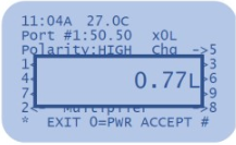
- Press 0=PWR to engage power supply and turn on pumps
- Ensure the screen is displaying a volume count
- Repeat steps 1 and 2 on all ports with connected tanks (pulsers)
- When volume data is displaying correctly for all tanks, connect the Fuel Lock device to the Fuel Lock app
Notes:
- A “No pulses detected” message during test fill indicates a wiring or pulser issue. Refer to third-party supplier instructions
- When using the Flow Testing Tool to test the pulser tubes, ensure that the pulse setting on the screen should say “10.00” or “1.00”. First test with a “1.00” pulse rate and if that is not reading correctly, try a “10.00”
- If the testing tool pulse rate is set to something outside of those values it can make testing difficult with those pulser tubes
Check J16
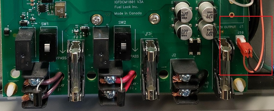
This connection is the one that powers the pulser (Flow Meter) board
- Ensure it is connected
- Ensure the J16 connector is connected properly and of the correct orientation
- The wires should be pointing down
- If it is connected the other way around, it could destroy the flow meter board
- The red wire should be on the left and black on the right
- If these wires are swapped, it will destroy the flow meter board
Check the wires on the right side of the motherboard are connected to the bottom screws
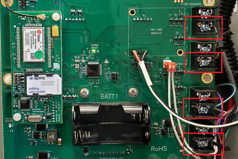
Note:
- From top to bottom on lower terminal on main PCB the order goes as WHITE ON J10, BROWN ON J11, GREEN ON J12, BLUE ON J13.
Check Flow Meter Board
Multimeter required.
Test terminals 6 & 7 on the Flow Meter Board
The red wire should be on terminal 7 (left) and black should be on terminal 6
- The multimeter should read 34V DC. If getting 34V, this means the flow meter board is getting power
- If J16 is disconnected or wiring issue is present while testing terminals 6 and 7 on the flow meter board, it will not give 34V
Test terminals 5 & 6
- This should give 5V. If not, it is likely a faulty flow meter board and will need to be replaced
Check for any damages (e.g. burn marks or blown resistors)
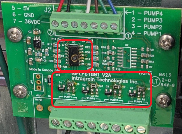
Ensure proper orientation of wiring on top of pulser board and terminals are tight
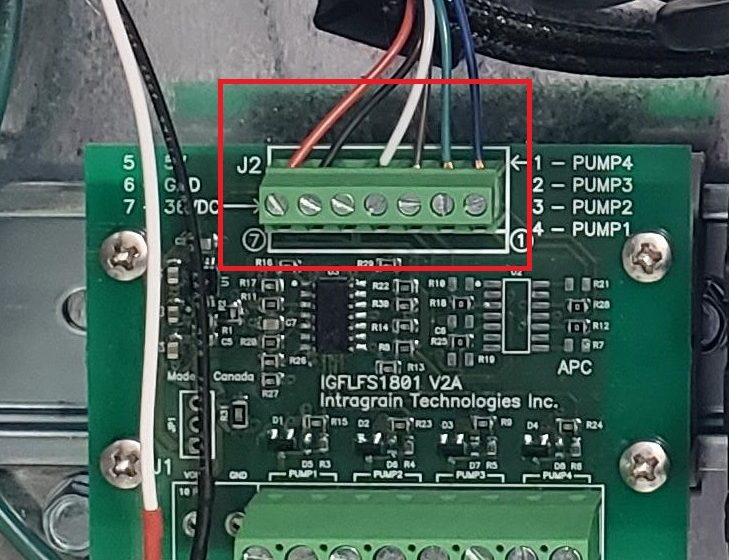
- From left to right: RED, BLACK, SPACE, WHITE, BROWN, GREEN, BLUE
Note that terminal 1 is on the right and terminal 7 is on the left.
Confirm correct wiring
- If the flow meter board is confirmed working, re-check pulser wiring to ensure correct installation
- Refer to pulser manufacturer’s installation manual
- If the issue still persists after replacing the pulser and the flowmeter board with a different one.
Move pump to another slot on the flow meter board
- If there are any available slots, try moving the pulser wires to an open slot to confirm whether the issue is slot-specific
- Alternatively, try swapping the problem pump to another known working slot and vice versa